
You pull the trigger. The wire feeds. The arc starts. And instead of that smooth, steady crackling sound your MIG welder should make, you get something else. Popping. Sputtering. Surging. The arc cutting out mid weld. Maybe the bead looks inconsistent, heavy spatter everywhere, poor wetting at the toes. You have tried adjusting the voltage knob and swapping wire. Nothing seems to help.
Arc instability is frustrating. It makes you wonder if your machine is broken, if you bought the wrong welder, or if you are just not cut out for this.
Chances are none of those things are true.
This article gives you a complete arc stability diagnostic system. You will learn what instability pattern you are seeing, the most likely cause in priority order, and the exact fix for each cause. Start with settings (the most common culprit). Work through to consumables. By the end of this guide, you should be able to get a steady arc within one welding session or know exactly when the problem needs professional repair.
If you have already read our article on why your MIG welder is popping, consider that a narrow deep dive into one symptom. If your main symptom is excessive spatter, our spatter guide is the narrower next read. This guide covers the full range of arc instability: popping, sputtering, surging, arc wander, harsh spattery arc, and intermittent arc loss. Six patterns, one diagnostic system.
Quick Answer: What Causes MIG Arc Instability and How to Fix It
Arc instability happens when something interrupts the stable transfer of current from the wire through the arc to the workpiece. The most common causes follow a predictable priority order. Fix them in this order and you can resolve most instability problems.
| If Your Arc Does This | Most Likely Cause | Quick Fix | Priority |
|---|---|---|---|
| Loud popping, like a chain-gun or popcorn | Voltage too low or wire speed too high | Increase voltage 1-2V or reduce wire feed speed | 1st: Check settings first |
| Sputtering, crackling, uneven burn rate | Wire feed stuttering: kinked liner, worn drive rolls, spool drag | Check liner, drive rolls, spool tension | 2nd: Check wire feed |
| Surging: arc gets hot then cold cyclically | Ground clamp loose or poor contact | Clean and tighten ground connection | 3rd: Check ground |
| Arc wanders or will not stay on one spot | Shielding gas issue: low flow, wrong mix, or draft | Verify gas flow 20-30 CFH, check for drafts | 4th: Check gas |
| Arc sounds rough with heavy widespread spatter | Gun angle too steep or stickout too long | Reduce drag angle to 10-15 degrees, stickout to 3/8-1/2 inch | 5th: Check technique |
| Arc cuts out intermittently mid weld | Worn or loose contact tip | Replace contact tip | 6th: Check consumables |
What Does a Stable MIG Arc Sound and Look Like?
Before you can diagnose instability, you need a baseline. What should a stable MIG arc sound and look like?
The Stable Arc Reference
What to hear. A stable MIG arc produces a consistent, steady crackling sound. Experienced welders call this the bacon frying sound. It is crisp and even, not too loud and not too quiet. No irregular pops. No long silent gaps. Just a steady, repeating crackle as the wire melts into the weld pool.
What to see. The arc is bright and steady. The column of ionized gas between the wire tip and the workpiece stays centered. It does not jump around or flicker. The weld pool wets evenly into both sides of the joint without excessive boiling.
What the bead looks like. Consistent width and reinforcement from start to finish. Minimal spatter. Smooth toes that blend into the base metal. No pinholes, no rough surface, no inconsistent bead shape.
If your arc does not match this baseline, work through the six patterns below to identify your specific instability type.
Six Arc Instability Patterns: Match Your Symptom to the Cause
Every arc instability pattern points to something specific about what is wrong. The way your arc behaves directs you to the most likely root cause. Use this table to match your symptom to the right starting point.
| Pattern | What You Hear and See | Most Likely Root Cause | Start Diagnosis At |
|---|---|---|---|
| Pattern 1: Loud Popping (chain-gun / popcorn) | Loud, irregular pops; bead has large spatter globules; poor wetting | Voltage too low relative to wire speed | Step 1: Settings |
| Pattern 2: Fine Sputtering / Crackling | Rapid, irregular sputtering; fine spatter spray; bead uneven | Wire feed inconsistency: liner kinked, drive rolls slipping, spool drag uneven | Step 2: Wire Feed System |
| Pattern 3: Surging (hot-cold-hot) | Arc brightens and dims cyclically; penetration varies along weld | Ground circuit problem: poor clamp connection, rusted work table, undersized ground cable | Step 3: Ground Circuit |
| Pattern 4: Arc Wander (wont stay on spot) | Arc jumps away from joint; bead wanders off line; hard to direct | Shielding gas issue: low flow, wrong mix, cross-draft, or gas leak | Step 4: Shielding Gas |
| Pattern 5: Harsh / Spattery (rough arc) | Arc sounds rough and harsh; excessive spatter covering wide area | Gun angle too steep (drag over 20 degrees) or stickout over 3/4 inch | Step 5: Technique |
| Pattern 6: Intermittent Arc Loss (cuts out) | Arc stops and restarts mid weld; wire feeds but no arc; then arc returns | Contact tip worn, loose, or wrong size; burnback damage | Step 6: Contact Tip |
Find your pattern in the table. Then jump to the corresponding diagnostic step below. If you are unsure which pattern fits, start at Step 1 and work through the full workflow in order. Settings are the most common cause, so starting there rarely wastes time.
Step-by-Step Diagnostic Workflow
Work through these six steps in order. Each step includes a checklist or diagnostic table you can use at the workbench. Do not skip steps. The most common causes are at the top.
Step 1: Check Your Settings First (Most Common Cause)
Settings mismatch is the number one cause of arc instability for DIY welders. Voltage and wire feed speed must be balanced. If voltage is too low for the wire speed, the wire feeds faster than the arc can melt it. This causes popping and stubbing. The wire literally stabs into the weld pool instead of melting cleanly.
If voltage is too high, the arc becomes harsh and uncontrolled. The weld pool gets too fluid. You see excessive spatter and the bead flattens out or undercuts.
How to adjust. Start with the settings chart on your machine. Every MIG welder comes with a recommended range for wire diameter and material thickness. Use that as your starting point. Then tweak in small steps. Change voltage 1V at a time. Weld a test bead. Listen to the arc. Adjust until you get that steady bacon frying sound.
| Symptom | Diagnosis | Adjustment | Note |
|---|---|---|---|
| Loud popping, stubbing, wire stabs into puddle | Voltage too low / wire feed speed too high | Increase voltage 1V at a time OR decrease wire feed speed | Most common cause for beginners |
| Harsh arc, fine spatter spray, bead flat and wide | Voltage too high / wire feed speed too low | Decrease voltage OR increase wire feed speed 10 percent | Also check gas mix if spatter persists |
| Arc surges and sputters together | Both settings may be off | Reset to machine chart, then tune from there | Use manufacturer recommended starting point |
| Arc sounds okay but bead has inconsistent width | Settings borderline | Fine-tune voltage plus or minus 0.5V until bead wets evenly | Small adjustments matter |
Your target sound: Steady, consistent crackling. Not popping. Not hissing. Not surging. If you hear any of those, keep adjusting.
Step 2: Check the Wire Feed System (Liner, Drive Rolls, Spool)
If your settings are correct but the arc still sputters or crackles, the wire feed system is the next place to look. The arc can only be stable if the wire feeds smoothly and consistently. Every time the wire feed stutters, the arc flickers.
The wire feed system has five checkpoints. Inspect them in this order.
| Component | What to Check | Pass/Fail Criterion | Fix |
|---|---|---|---|
| Liner | Remove the liner from the gun. Inspect for kinks, dirt, rust, or debris. Feed a length of wire through the disconnected liner by hand. | Wire slides freely with no catching or binding | Replace liner if kinked or rusty; clean if dirty with compressed air |
| Drive rolls | Inspect the groove for wear, flat spots, burrs, or caked debris. Confirm the groove size matches your wire diameter. | Rolls match wire size, groove clean with sharp edges | Replace if worn or mismatched |
| Drive roll tension | With the wire aimed at an insulated surface (wood block), squeeze the trigger. The wire should feed without slipping under moderate resistance. | Wire feeds steadily without slipping at the drive rolls | Adjust tension knob 1/4 turn at a time. Too tight deforms wire; too loose causes slipping |
| Spool drag | Squeeze the trigger briefly. The spool should rotate freely without overrunning when the trigger releases. | Spool stops almost immediately when trigger released | Tighten center spool nut if overrunning; loosen if feed drags |
| Inlet guide | Check alignment between the spool, inlet guide, and drive rolls. The wire should enter the drive rolls in a straight line. | Wire feeds in a straight line with no side-bending at the inlet | Realign the inlet guide if the wire enters at an angle |
A quick liner test. With the gas nozzle and contact tip removed, pull several feet of wire out through the gun. If the wire feeds smoothly with the gun bent in various positions, the liner is likely fine. If you feel resistance or hear a scraping sound at a particular bend angle, the liner is kinked or dirty at that spot.
Step 3: Check the Ground Circuit (More Important Than Most DIY Welders Think)
The ground circuit is the most overlooked cause of arc instability in DIY welding content. A poor ground connection causes the arc to surge. It gets hot, then cold, then hot again. You can hear it cycle. You can see it in the bead: inconsistent penetration, varying bead width, a pattern of light and dark along the weld.
Why does this happen? The ground clamp is supposed to complete the welding circuit with minimal resistance. If the resistance at the ground point fluctuates because of rust, paint, or a loose clamp, the current at the arc fluctuates too. The welder tries to compensate, which makes the surging worse.
Safety note: The ground circuit carries full welding current. A poor ground is not just a stability problem. It is an electrical safety hazard. Check the ground cable for damage and the clamp for secure contact before every session.
| Checkpoint | What to Look For | Fix |
|---|---|---|
| Clamp connection point | Clean bare metal: no rust, paint, oil, or mill scale | Grind to bright metal at the connection point |
| Clamp spring tension | Clamp holds firmly with no wobble or side play | Tighten or replace the clamp if loose |
| Ground cable | No cuts, frays, or heat damage along the full length | Replace if damaged. Undersized or corroded cable adds resistance |
| Workbench / table surface | Rusty or painted surface between the ground point and the weld | Connect the ground clamp directly to the workpiece, not to the bench surface |
| Ground location | Ground point is far from the weld area | Move the ground clamp as close to the weld joint as practical |
| Quick test | Touch ground clamp to clean scrap. Strike an arc on a practice piece. Arc runs steady with no surging. | If surging persists, inspect the ground cable and clamp more thoroughly |
The rusty table problem. Many DIY welders clamp their ground to a steel workbench that looks solid but has a layer of rust or paint at the contact point. The clamp makes intermittent contact through that layer. The arc surges. The welder assumes a bad machine. The real fix is grinding a clean spot on the bench or clamping directly to the workpiece.
Where to put the ground clamp. Connect it as close to the weld joint as possible. Every inch of distance between the ground clamp and the weld adds resistance to the circuit. On large pieces, move the clamp closer. Do not rely on the workbench as a conductor between distant points.
Step 4: Check Shielding Gas (Flow, Mix, Leaks, Drafts)
Gas issues produce a distinct arc instability pattern: arc wander. The arc tries to burn, but the shielding is inadequate or wrong. The arc jumps away from the joint. You struggle to keep the bead on line.
Shielding gas does more than protect the weld pool from atmospheric contamination. It also directly affects arc characteristics. Wrong flow, wrong mix, or a cross-draft can all destabilize the arc.
| Issue | Effect on Arc | Fix |
|---|---|---|
| Flow too low (below 15 CFH) | Arc becomes erratic; porosity may appear | Increase regulator to 20-30 CFH |
| Flow too high (above 35 CFH) | Turbulence pulls air into the shielding; arc sputters | Reduce regulator to 20-30 CFH |
| Wrong gas mix (100% CO2) | Rougher arc, more spatter, narrower stable range | Consider C25 (75/25 argon/CO2) for a smoother arc |
| Cross-draft in work area | Arc wanders; shielding lost; porosity appears | Block drafts with welding screens; move work indoors |
| Gas leak at connections | Intermittent arc issues combined with porosity | Soap-test connections; tighten fittings |
| Tank almost empty | Flow may drop mid-weld; arc becomes unstable | Check tank pressure before starting each session |
How to set gas flow. Open the cylinder valve fully (two full turns minimum). Squeeze the trigger to start gas flow. Adjust your MIG gas regulator to 20-30 CFH while gas is flowing. Do not set the flow rate with gas static and assume it stays correct under flow.
C25 vs. CO2. If you are running pure CO2, expect a rougher arc with more spatter. CO2 has a narrower stable operating window than C25. If your arc has always felt harsh on CO2 and you have checked everything else, switching to C25 may be the fix. This is not a claim that C25 fixes all instability. Some machines and applications work fine with CO2. But if you have the option, C25 makes the arc more forgiving.
Cross-draft check. A fan, an open garage door, or even body movement can create enough airflow to disrupt gas shielding at the weld pool. If your arc wanders and you work near a breeze, block it. Even a slight draft that you barely feel can move enough gas to cause arc instability.
Step 5: Check Gun Angle and Stickout (Technique Factors)
Technique errors amplify arc instability that starts with settings or equipment. Even with perfect settings, wrong gun angle or excessive stickout produces an unstable arc.
Drag angle. MIG welding on steel uses a drag (pull) technique. The gun points back toward the completed weld at an angle of 10-15 degrees from vertical. If you push the gun (angle past vertical), or if your drag angle is steeper than 15-20 degrees, you create turbulence in the gas shielding. The arc becomes harsh and spattery. Spatter lands heavily on one side of the joint.
Stickout. Stickout is the distance the wire extends past the contact tip. The correct range is 3/8 to 1/2 inch (10-12 mm). If stickout exceeds 3/4 inch, the current drops significantly by the time it reaches the arc. The arc loses power. It pops and sputters because there is not enough energy to transfer metal cleanly. If stickout is too short (under 1/4 inch), the contact tip gets too close to the weld pool, risking burnback and spatter buildup on the tip.
| Technique Element | Correct Range | What Happens When Wrong |
|---|---|---|
| Drag angle (push for aluminum) | 10-15 degrees from vertical | Over 20 degrees: arc harsh, spatter on leading side, gas entrainment |
| Stickout | 3/8 to 1/2 inch (10-12 mm) | Over 3/4 inch: arc loses power, pops and sputters; under 1/4 inch: burnback risk |
| Travel speed | Steady: stay ahead of puddle but let it wet | Too fast: arc stretched, popping; too slow: puddle boils, bead piles up |
| Gun centerline | Pointed into joint center | Off-center: arc pulls to one side, uneven fusion |
A quick technique test. Weld a straight bead on a clean scrap plate at your normal angle. Then weld another bead with a slightly shallower angle (closer to 10 degrees) and shorter stickout. If the second bead runs smoother, your technique was the problem.
Step 6: Check the Contact Tip (Wear, Size, Tightness)
The contact tip is the last electrical connection before the arc. It transfers current to the wire as it passes through. If that connection is worn, wrong-sized, or loose, the arc cannot stay stable.
Contact tips are consumables. They wear oval over time. They accumulate spatter buildup on the face. They loosen from repeated heating and cooling cycles. And after a burnback event (wire fusing to the tip), the tip must be replaced immediately. For a complete guide on MIG gun consumables including proper selection and installation, see our MIG gun setup guide.
Contact tip inspection decision guide.
Start here: Is the tip orifice round?
- Yes: Check tightness. Is the tip tight in the gun?
- Yes: Tip is likely OK. Move on.
- No: Tighten the tip. Test the arc.
For a broader troubleshooting map, pair this guide with the wire feed problems guide, the systematic setup checklist, and the defects chart. They help when arc instability is just the visible symptom of a wider feed or tuning issue.
- No (oval, worn, or enlarged): Replace the tip. Test the arc.
Is the tip face covered in spatter buildup?
- Yes: Clean with a tip cleaner or replace. Test the arc.
- No: Proceed.
Did you recently have a burnback event?
- Yes: Replace the tip immediately. Burnback welds the wire to the inside of the tip, creating a high-resistance connection even if the wire broke free. The arc will be intermittent until the tip is replaced.
- No: Proceed.
Size matching. The contact tip must match your wire diameter exactly. A 0.030 tip with 0.030 wire. A 0.035 tip with 0.035 wire. Using the wrong size causes poor electrical contact and arc instability. If you recently switched wire diameters, verify the tip size matches.
Nozzle condition matters too. Spatter buildup inside the nozzle restricts gas flow. A restricted gas flow produces the same arc wander symptoms as a low flow setting. Clean the nozzle regularly. Use anti-spatter spray to reduce buildup.
Arc Stability Troubleshooting Flow Chart
This text-based flow chart gives you a single decision path to follow at the workbench. Start at the top. Work through each step. Do not skip ahead.
Start here: Arc unstable?
    |
    v
Step 1: Settings checked?  No  -> Adjust voltage/WFS  -> Arc stable? -> Yes, Done
    | Yes                                               |
    v                                                   No (continue)
Step 2: Wire feed checked?  No  -> Inspect liner, drive rolls, spool -> Arc stable? -> Yes, Done
    | Yes                                                 |
    v                                                     No (continue)
Step 3: Ground checked?  No  -> Clean and tighten ground -> Arc stable? -> Yes, Done
    | Yes                                                 |
    v                                                     No (continue)
Step 4: Gas checked?  No  -> Verify flow, mix, drafts -> Arc stable? -> Yes, Done
    | Yes                                                 |
    v                                                     No (continue)
Step 5: Technique checked?  No  -> Adjust angle, stickout -> Arc stable? -> Yes, Done
    | Yes                                                   |
    v                                                       No (continue)
Step 6: Contact tip checked?  No  -> Inspect / replace tip -> Arc stable? -> Yes, Done
    | Yes                                                     |
    v                                                         No (continue)
Still unstable? -> See "When Arc Instability Means a Bigger Problem"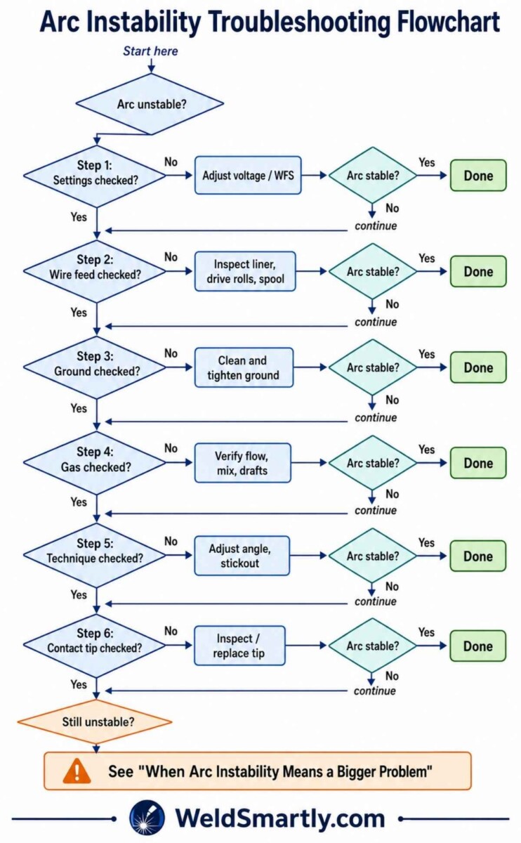
Pre-Weld Arc Stability Checklist
Run this 30-second checklist before every welding session. It prevents most arc instability problems before they start.
Settings. Voltage within recommended range for wire diameter and material. Wire feed speed matched to voltage. Machine settings chart used as starting point.
Wire feed. Spool turns freely without drag. Liner not kinked. Drive rolls clean and matched to wire size. Roll tension set correctly (wire feeds without slipping under moderate resistance).
Ground. Clean bare metal contact point. Clamp tight and secure. Cable undamaged along full length. Ground clamp close to weld joint.
Gas. Cylinder has pressure (check before starting). Flow set to 20-30 CFH. Correct gas mix for material. No drafts near work area.
Technique. Stickout approximately 3/8 to 1/2 inch. Gun angle 10-15 degrees drag. Comfortable body position to maintain steady travel speed.
Consumables. Contact tip tight in the gun. Orifice round. No spatter buildup on tip or inside nozzle. Nozzle clean.
Common Arc Stability Myths
Some persistent misconceptions lead DIY welders to chase the wrong fix. Here is what you need to know.
| Myth | Fact |
|---|---|
| My welder is broken. That is why the arc is unstable. | Most arc instability is caused by settings, wire feed problems, or ground issues, not a machine defect. Check settings before assuming machine failure. |
| Arc instability is the same as spatter. | Spatter is a symptom of arc instability, not the same thing. Fix the arc stability and spatter reduces automatically. For spatter reduction, see our spatter guide. |
| A bad ground just means the weld is weaker. | A poor ground causes arc surging that affects penetration, bead consistency, and can damage the welder internal electronics over time. |
| Arc instability means I need to turn up the wire speed. | Often the opposite. Wire speed being too high for the voltage is a primary cause of popping and instability. |
| Contact tips last forever. | Contact tips are consumables that wear oval with use. An oval tip causes intermittent arc contact and instability. Replace tips regularly. |
| Pure CO2 gives the same arc stability as C25. | CO2 produces a harsher, more unstable arc than C25. If you are running CO2, expect more spatter and a less forgiving arc. |
When Arc Instability Means a Bigger Problem
If you have worked through all six diagnostic steps and the arc is still unstable, the problem may be internal to the welder. This is not common, but it happens.
Signs of internal machine problems. Burning smell coming from the welder. The breaker trips repeatedly. Visible smoke. Arc instability that follows the machine to different outlets and different work locations.
Check the simple things first. Before assuming internal failure, rule out line voltage issues. A long or undersized extension cord can cause voltage drop that looks like arc instability. For 120V MIG welders, use a 12-gauge cord no longer than 50 feet. For 240V machines, follow the manufacturer cord specifications. A loose wall receptacle can also cause intermittent power delivery.
When to call a professional. If the machine produces burning smells, trips breakers, or shows any sign of internal electrical fault, stop using it immediately. Contact a certified welding equipment technician. If the welder is under warranty, contact the manufacturer.
Warning: Do not open the welder cabinet. Internal components, including capacitors, retain dangerous voltages even when the welder is unplugged. Capacitors can hold a lethal charge for hours or days after power is disconnected. Internal repairs should only be performed by qualified technicians.
FAQ
Can a bad extension cord cause arc instability?
Yes. An undersized or very long extension cord causes voltage drop at the welder. The machine does not receive full voltage, so the arc behaves as if the voltage setting is too low. For a 120V MIG welder, use a 12-gauge cord no longer than 50 feet. For 240V machines, follow the manufacturer cord specifications. If the cord feels warm during use, it is too small for the load.
Does arc instability damage my welder?
Intermittent instability from settings or consumables will not damage the welder. But a sustained poor ground connection can overheat internal components. Surging from a bad ground should be fixed promptly. If the welder runs with a poor ground for extended periods, the internal circuitry works harder to compensate, which reduces component lifespan.
Why does my arc only get unstable after a few minutes of welding?
This pattern often points to a temperature-related issue. Drive roll tension may loosen as the machine warms up. Gas flow may drop as the regulator warms and pressure changes. An extension cord that overheats and increases resistance can cause voltage drop over time. Also check the ground clamp position: as the workpiece heats, the contact surface can oxidize and increase resistance.
Conclusion
Arc instability is frustrating. But in the majority of cases, the fix is straightforward once you know where to look.
Start with the six pattern identification table to match your arc symptom to the most likely cause. Then work through the diagnostic workflow in order: settings, wire feed, ground, gas, technique, contact tip. Do not skip steps. Settings are the most common cause for 8 out of 10 instability cases.
Run the pre-weld checklist before every session. It takes 30 seconds and prevents most problems before they start.
If you have checked everything and the arc is still unstable, consult a qualified technician. Some problems need professional tools and experience.
Related reading on Weldsmartly:
- Why your MIG welder is popping: a narrow deep dive into popping-only symptoms
- MIG welding burnback causes and fixes: what to do when wire fuses to the contact tip
- MIG welding porosity troubleshooting: when arc instability comes with pinholes and wormholes
- Remove welding spatter: cleanup guide for existing spatter
- How to fix a bad weld: general troubleshooting for multiple weld defects